http://pinballparts.x10host.com/wp-content/uploads/2026/04/Bridge_Board_User_Manual-7.pdf
http://pinballparts.x10host.com/wp-content/uploads/2026/05/Bridge_Board_Install_Instructions_MJ_v1_PDF_small.pdf
Bridge Power Board User Manual
Important Disclaimer
This product is intended for use by individuals with appropriate technical knowledge of electrical systems.
Installation involves working with potentially hazardous voltages and improper handling may result in equipment
damage, personal injury, or fire.
By installing or using this board, the user assumes all responsibility for any risks associated with its use. The
designer and distributor of this board shall not be held liable for any damage to equipment, property, or persons
resulting from improper installation, misuse, or failure to follow recommended procedures.
Installation is performed at the user’s own risk. If you are unsure about any aspect of the installation process,
consult a qualified technician before proceeding.
- Introduction
The Bridge Power Board is a modernized power rectification and filtering solution designed to replace aging and
failure-prone components in legacy pinball systems. Traditional designs often relied on discrete rectifiers and large
electrolytic capacitors that degrade over time, leading to unstable voltage levels and increased system risk. This
board consolidates these functions into a compact and reliable module, significantly improving electrical
performance and long-term reliability.
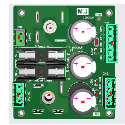
Figure 1: Bridge Power Board Overview
- Purpose of the Board
The primary purpose of this board is to address known design weaknesses in older systems, including the
absence of proper fuse protection and the degradation of high-value capacitors. By integrating modern
components and protective features, the board minimizes the risk of catastrophic failures such as transformer
damage, wiring burnout, or excessive current flow. - Key Features
• High-current bridge rectifiers (35A, 1000V)
• Multiple capacitors for improved filtering and lower ESR
• Integrated fuse protection
• LED indicators for voltage presence
• Zener diode voltage regulation
• Screw terminal connections for easy installation
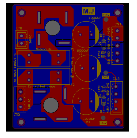
Figure 2: PCB Layout
- Technical Specifications
The board operates using dual AC inputs and provides stable DC outputs for both solenoid and lamp circuits.
High-current components ensure reliable performance under load, while parallel capacitors improve ripple
suppression and extend system lifespan.
• Input: 26VAC (solenoids), 14VAC (lamps)
• Output: ~34VDC, ~18VDC
• Bridge Rectifiers: 35A, 1000V
• Capacitors: 10,000 µF (multiple)
• Fuse Rating: 8A slow-blow
• Zener Diodes: 24V and 10V - Safety Information
Always follow proper safety procedures when working with electrical systems. Ensure the system is powered off
and disconnected before installation. Capacitors may retain charge after power is removed, so they must be
discharged safely before handling.
• Disconnect power before installation
• Discharge capacitors before handling
• Verify all wiring connections
• Use correct fuse ratings - Installation Procedure
Begin by removing the existing bridge rectifiers and large filter capacitor from the system. Carefully cut or desolder
all connected wires, ensuring that each wire can be identified later. Any jumper wires between the rectifiers and
capacitor should also be removed, as they are no longer required.
Once the original components have been removed, route the wires to the new board and secure them using the
screw terminal connectors. Ensure that all connections are firmly tightened to prevent high-resistance joints, which
can lead to overheating.
After completing all connections, visually inspect the board to confirm correct wiring before applying power. It is
recommended to power the system initially with appropriate precautions, such as using a current-limited supply or
inline fuse protection.
6.1 Wire Mapping: Original System to New Board
Before installing the board, identify and label the wires connected to the original bridge rectifiers and capacitor.
These wires will be reconnected to the new board using the screw terminals. The table below describes where
each wire originates and where it should be connected on the new board.
The following mapping has been verified on a Williams System 11A machine (High Speed), which uses standard
color conventions. Other systems such as Data East and early Sega machines are generally compatible, but wire
colors and configurations may vary. Always verify connections before applying power.
Figure 3: Wiring Diagram
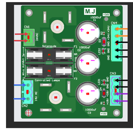
6.2 Verified Wiring Connections (Williams Systems)
• CN1 (26VAC Input – Solenoid Supply): Connect the two red or red/white wires from the transformer
secondary. Polarity is not important for AC input.
• CN2 (14VAC Input – Lamp Supply): Connect the two blue or blue/white wires supplying AC voltage for
controlled lamps. The center pin may remain unused depending on the wiring harness.
• CN3 (18VDC Output – Lamp Circuit): Connect violet wires to the positive terminals and black wires to ground.
This output supplies rectified and filtered voltage for controlled lamps.
• CN4 (34VDC Output – Solenoid Circuit): Connect orange wires (or orange/blue in some systems) to the
positive terminals and black wires to ground. This output supplies power to coils and solenoids.
6.3 Critical Warning: Bridge Rectifier Terminals
Do NOT connect any wires directly to the metal terminals (tabs) of the bridge rectifiers mounted on the board.
These terminals are part of the internal rectification circuit and are not intended for external wiring connections.
Connecting wires to these terminals can result in incorrect circuit operation, short circuits, or severe damage to the
board and connected components. In high-current systems, this may also pose a fire risk or damage upstream
components such as the transformer.
All electrical connections must be made ONLY through the designated screw terminal connectors (CN1–CN4) as
labeled on the board. These connectors are specifically designed to safely handle the required currents and
ensure correct circuit operation.
6.4 Compatibility Notes
While this board has been tested on a Williams System 11A machine, it is also compatible with many Williams,
Data East, and early Sega systems that use similar power architectures. However, wire colors and harness
configurations may differ between models.
In some older systems, additional wires (such as flipper or auxiliary power lines) may be tied into the same nodes
as the main supply lines. These wires should remain grouped together and connected to the corresponding
terminals on the new board.
If wire colors do not match the descriptions provided, trace the wires based on their function rather than relying
solely on color identification.- Operation
During operation, AC voltage is converted to DC through bridge rectification. The resulting DC voltage is filtered
using high-capacity electrolytic capacitors, ensuring a stable output. Zener diodes provide voltage clamping, and
LED indicators offer a visual confirmation of system status. - Troubleshooting
If the board does not operate correctly, check all wiring connections and fuse conditions. LED indicators can assist
in diagnosing whether output voltage is present.
• No output: check AC input and fuse
• Dim output: inspect capacitors
• Fuse blowing: possible short circuit
• LED off: verify voltage and polarity - Maintenance
Routine inspection is recommended to ensure long-term reliability. Check for loose connections, damaged
components, or capacitor wear. Replace components as necessary to maintain performance. - Conclusion
This Bridge Power Board provides a robust and modern replacement for legacy systems. By combining improved
protection, filtering, and ease of installation, it significantly enhances system safety and performance.